Filter for supply voltage of amplifiers Circuit Diagram Variable Low-Pass Filter. Here we use a small value cap (500pf up to 50nf is a good range for experimentation) wired in the signal path of a circuit. If the pot's wiper is at the full open position (no resistance) the signal will bypass the cap and go straight through.

The low pass filter circuit which is the prime part of this project, filters a frequency spectrum or any mix of frequencies. The frequencies above the cut-off frequency of the circuit are bypassed to the ground by the capacitor C. This is a capacitive low pass filter which has a resistor connected in series and a capacitor in parallel with the output.

PDF Basic Introduction to Filters Circuit Diagram
Next, high pass filter is designed to attenuate frequencies from 0 to 9.75 kHz. Cut-off frequency is set to 9.75 kHz and standard capacitor value for audio circuit design chosen to be 0.01 micro Farads. To calculate Resistor values for High pass filter Equation 2 is used. Where: m = magnitude coefficient f c = 9.75 kHz Cs = 0.01 micro Farads D
For example, hi-fi audio goes down to 20 Hz. For some headroom, it's a good idea to design your circuits with high pass filter rolloffs at 10 Hz or so. The impedance magnitude of a capacitor is 1 / 2πfC, with f in Hz, C in Farads, and the result in Ohms. This helps ensure that the audio signal is of the highest possible quality. The most common type of noise filter circuit is a passive low-pass filter. This uses inductors and capacitors to block higher frequency signals and allow lower frequencies to pass. Other types of filter circuits include high-pass filters, notch filters and bandpass

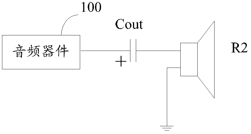
How to choose a capacitor for filtering an audio signal? Circuit Diagram
A filter is a device that passes electric signals at certain frequencies or frequency ranges while preventing the passage of others. — Webster. Filter circuits are used in a wide variety of applications. In the field of telecommunication, band-pass filters are used in the audio frequency range (0 kHz to 20 kHz) for modems and speech processing.